

Shows both active and inactive outputs. In the image above, Output 1 is currently active (indicated by shading), while Output 2 remains inactive. The display dynamically adjusts based on how many outputs are connected to the panel. For active outputs, the timer displays the remaining time until deactivation. For inactive ones, it shows the countdown until activation.
Indicates the status of Inputs 1 through 4. Active inputs are visually represented with shading.
Displays the amperage draw of any active output. For panels with more than five outputs, current sensing information appears on an additional screen.
A cell tower icon on the screen indicates server connectivity.
Displays the current cell signal strength. The panel intelligently selects the optimal carrier based on signal quality.
The date appears in the format:day.month.year (DD.MM.YY).
Users can choose between a 12-hour or 24-hour clock format via the Date/Time settings menu.
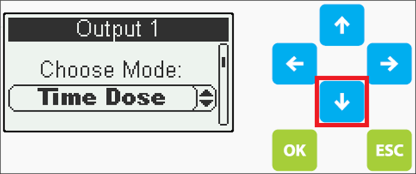
Navigation keys for accessing and moving through the control panel interface

The Customer Menu provides access to the core functions of the control panel. It can be reached by pressing the Down arrow on the main screen. No password is required to enter this menu.

Overview of device details, including firmware version, serial number, variant specifications, and manufacturing date.
The Function Test enables users to quickly cycle through all active outputs to confirm correct operation and monitor amperage levels. During the sequence, it systematically tests each enabled output, activates the alarm, and verifies the status of the backup battery.
Enables operator(s) to activate a designated output for a limited duration. The runtime is preset during the system's configuration phase.
Detailed summary of output operation times, organized by calendar week.
Provides the user with the ability to adjust the system’s date and time settings.
Enables users to adjust contrast, brightness, and illumination parameters.
Select the preferred operating language
Performs a soft reset of the panel
The Function Test enables users to quickly cycle through all active outputs to confirm correct operation and monitor amperage levels. During the sequence, it systematically tests each enabled output, activates the alarm, and verifies the status of the backup battery.

To initiate a Function Test, press OK on the Function Test option in the menu, then scroll to Start Test and press OK again. A preset countdown will begin, after which the first active output will turn ON for its designated cycle duration. During this period, the output’s current will be displayed at the bottom of the screen.

If you wish to skip the current output or proceed to the next one, press OK to bypass the remaining cycle time. Once all outputs have been tested, the system will automatically evaluate the visual and audio alarms, along with the backup batteries.
Manual Mode enables operator(s) to activate a selected output for a limited duration, with the runtime preset during system configuration.

To activate Manual Mode, select the Manual Mode option from the menu and press OK.
Within the Manual Mode menu:
-
Scroll to the Output you wish to control and press Select.
-
Use the Up or Down arrows to choose one of the following modes:
-
Automatic: Follows the Output’s predefined configuration.
-
Always ON / Always OFF: Temporarily enables or disables the Output based on the manual run time setting.
-
After selecting your desired mode, press OK to confirm. To exit the Manual Mode menu, press ESC.

-
Active Inputs can be viewed on the panel’s Main Screen. At the bottom of the display, Inputs 1 through 4 indicate their status—shaded icons represent active Inputs.

If the control panel contains more than four inputs, the extended Inputs screen must be accessed to view the status of the additional inputs. To do so, press the LEFT button while on the main screen.
The Main Menu, also known as the Operator Menu, provides access to the system’s core functions. From here, users can view and adjust key parameters such as outputs, inputs, run times, and other operational settings. This menu is secured by a password.
To open the Main Menu, press OK while on the main screen. If password protection is enabled, the system will prompt for a password.
-
Use the LEFT and RIGHT keys to navigate the cursor.
-
Use the UP and DOWN keys to adjust the numeric values.
If the password is unavailable or forgotten, please contact your system administrator for assistance.
Once the correct password is entered, full access to the Main Menu will be granted.

The Output Menu enables users to customize the behavior and input settings associated with each output.
The system maintains historical run-time data for each output, storing a rolling log covering the past 52 calendar weeks.
A chronological log of system activities and events recorded by the panel.
This section contains advanced configuration options, including Backup Alarms, GPRS settings, Manual Mode run time, Quiet Mode duration, and other extended functionalities.
This section contains advanced system functions and is intended for use by qualified service technicians only.
-
The panel interface offers the same functionality for programming outputs as the Series2 Software
Step-by-Step Instructions:
-
From the Main Menu, scroll down to Outputs.
-
Press OK to enter the Outputs section.
1. Access the Outputs Menu
-
Scroll through the list to locate the output you wish to configure.
-
Press OK to open the settings for the selected output.
2. Select an Output
3. Choose Operating Mode
-
Scroll down to Operating Mode.
-
Press OK to view available modes.
-
Scroll through the options and select the desired operating mode for the output.
-
Press OK to confirm your selection.
*Programming terms can be found below
⚠️ Note: Ensure you are familiar with the function of each operating mode before making changes. Refer to the Operating Mode Reference section for detailed descriptions.
Sets the selected output to a permanently inactive state.
Timed dosing enables an output to operate based on predefined Run Time and OFF Time intervals, allowing precise dosing of specific volumes. This method distributes effluent more evenly throughout the day compared to demand-based dosing.
Operation
Timed dosing is managed using floats or a water level transducer. Unlike motor-rated switches, the float used here is a signal float, which sends an electrical signal to the control panel when the effluent reaches a preset level. This signal activates the timer, initiating the dosing cycle.
Configuration Options
Timed dosing can be configured using the following setups:
-
2-Float Configuration
-
3 & 4-Float Configuration
-
Transducer-Based Configuration
⚠️ Ensure proper calibration of float levels or transducer settings to maintain consistent dosing performance.
-
Demand dosing initiates output operation immediately upon receiving an active Start signal. The output remains engaged until the input signal is deactivated, at which point operation ceases.
Configuration Options
Demand dosing can be configured using the following setups:
-
2-Float Configuration
-
3 & 4-Float Configuration
-
Transducer-Based Configuration
⚠️ Ensure proper calibration of float levels or transducer settings to maintain consistent dosing performance.
-
Aeration Mode enables the Blowers to operate either continuously or on a time-dosed schedule. This mode functions independently and does not require input signals to activate the settings.
Configuration Options
Default OFF input can be added to modify run cycles when water levels are low—reducing unnecessary aeration.
Time-dosed operation is compatible with various input configurations, including:
-
2-Float setup
-
3/4-Float setup
-
Transducer-based control
-
This function is purpose-built for applications requiring chemical dosing. It operates under the control of a master output, which initiates either a time-based or demand-based dose for the chemical pump.
Configuration Options
-
ON Delay & OFF Delay: Allows users to configure delays before starting or stopping the dose, ensuring flexibility if the dosing cycle needs to lag behind or extend beyond the master output’s timing.
-
Parallel Output Activation: Supports triggering a secondary output simultaneously, useful for running additional equipment or processes alongside the chemical pump.
-
Day/Night Mode enables users to configure separate run cycles for two distinct time periods—daytime and nighttime. This is ideal for systems that require more frequent output during the day and reduced activity at night.
Configurable Options
Users can program specific time blocks during the day when the output should remain OFF, allowing for greater control and energy efficiency.
Time-dosed operation in this mode supports the following input configurations:
-
2-Float setup
-
3/4-Float setup
-
Transducer-based control
-
The system maintains the output in a constant ON state
-
Output modules are equipped with an internal current sensor rated to handle the full load of the contactor. If you're using this built-in sensor, set the current source to Internal.
If you're installing an external current sensor, make sure to:
-
Select the correct External current setting on the panel.
-
Match the panel configuration to the specifications of the external sensor you're using.
⚙️ Current Source Selection: Choose the appropriate current source based on the sensor type and installation setup. Refer to the panel settings to ensure compatibility and accurate readings. Options are Internal, External 10A, External 20A, and External 50A

🔧 Setting Current/Amperage Thresholds
Configure both Minimum and Maximum current/amperage thresholds to ensure safe and reliable operation.
-
If the current drops below the Minimum threshold, the output will shut off automatically, and an alarm will trigger to alert the user that the current/amperage is outside the operating range.
-
If the current exceeds the Maximum threshold, the output will also shut off to prevent potential damage, and an alarm will activate.
⚠️ Recommendation: Set the Minimum current slightly above zero, but avoid placing it too close to the normal operating range to prevent false alarms.
📟 Navigation Tip: From the previous menu, scroll down to Min Current and press OK to adjust the setting.

🔧 Adjusting Minimum and Maximum Current Settings
To set the Minimum Current:
-
Use the interface buttons to navigate the setting.
-
Press the Left and Right keys to move the cursor.
-
Use the Up and Down keys to adjust the value.
-
Once the desired minimum current is set, press OK to confirm.
Next, scroll down to Max Current and press OK to begin configuration.

🔧 Overcurrent Configuration
Set the overcurrent threshold according to the maximum rated current of the output device in use. This ensures proper protection and prevents unnecessary shutdowns or equipment damage.
-
🔧 Output Programming via Panel Interface
When configuring outputs through the panel interface, only the parameters relevant to the selected Operation Mode will be shown. The interface dynamically updates based on your selections to streamline setup.
⚙️ Key Parameters Explained:
-
Run Time: Duration the system remains ON or doses during each cycle. Typically active when the float or signal is triggered.
-
OFF Time: Duration the system remains OFF or pauses dosing during each cycle.
-
Initial State: Defines whether the output begins with Run Time or Off Time when the signal is first activated at the start of a cycle.
-
Input Type: Choose the input configuration controlling the output (e.g., Pump, Blower). Options include 2 Inputs, 3/4 Inputs, or Transducers.
-
Start/Stop Signal: In a 2-input setup, this float manages ON/OFF dosing. In a 3/4-input setup, the Stop Float acts as a backup/redundant, while the Start Float controls ON/OFF operation.
-
High Level Alarm: Alerts the user to high water levels. This float is typically positioned at the top of the tank and serves only as a notification—it does not affect output timing.
-
Override Alarm: Activates additional dosing options when triggered. Users can:
-
Configure alternate Run Time and OFF Time or ON Demand (if field is left Empty)
-
Enable Duplex Slave output to double dosing capacity
-
Set an Override Notification
-
-
Override Run Time: Duration the system doses during an override condition.
-
Override OFF Time: Duration the system pauses dosing during an override condition.
-
Max No-Cycle: Limits the number of ON cycles allowed within a 24-hour period. If exceeded, an alarm notifies the user. This is a notification-only feature and does not interrupt output operation.
-
Max Cycle Time: Sets the maximum duration the output can run continuously between cycles. This is a notification-only feature and does not interrupt output operation.
-
Max Override Cycles: Triggers an alarm if the number of override cycles exceeds the set limit within a 24-hour period. Notification only—does not affect output behavior.
-
Per Cycle Duplex/Triplex: Alternates dosing across 2 or 3 outputs per cycle to balance load and increase efficiency.
-

